- Home
- Инструкции
- Автоматика для ворот
- MARANTEC
- CS 300
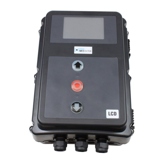
![]() Электронный блок управления MARANTEC CS 300 инструкция по эксплуатации на русском языке в формате pdf, размер файла 682.1 Kb. Используйте кнопки «Скачать инструкцию» или «Открыть в новом окне» (документ откроется в новом окне или вкладке браузера). Функция просмотра доступна при наличии плагина Adobe Acrobat в вашем браузере.
Электронный блок управления MARANTEC CS 300 инструкция по эксплуатации на русском языке в формате pdf, размер файла 682.1 Kb. Используйте кнопки «Скачать инструкцию» или «Открыть в новом окне» (документ откроется в новом окне или вкладке браузера). Функция просмотра доступна при наличии плагина Adobe Acrobat в вашем браузере.
MARANTEC CS 300 инструкция
Язык: Русский
Размер : 682.1 Kb
Формат файла: pdf
Добавлен: 13.07.2015
Руководство пользователя
Предварительный просмотр

Информация, описание, технические характеристики изделия
Описание и информация о технических характеристиках по данному изделию пока что отсутствует. Содержание во всех разделах сайта периодически обновляется. Попробуйте зайти на страницу позже.
Отзывы по оборудованию и комментарии к материалу
Здесь можно оставить свои отзывы по оборудованию «MARANTEC CS 300 — Блок управления», а также написать комментарии к материалу.
Главная » Инструкции » Автоматика для ворот » MARANTEC
![]()
MARANTEC CS 300 — Инструкция по установке и эксплуатации (RU) в формате pdf. Руководства по установке, настройке и эксплуатации оборудования.
Дата добавления: 25.12.2017
Размер файла: 682.1 Kb
Формат файла: pdf
Просмотров: 1463
Загрузок: 108
Дополнительная информация
По данному материалу пока нет информации.
Отзывы и комментарии
Отзывы и комментарии к материалу «MARANTEC CS 300 — Инструкция по установке и эксплуатации (RU)».
Кто вы? человек робот
-
Contents
-
Table of Contents
-
Bookmarks
Quick Links
CS300
Pro-Line
SYSTEM
Operating instruction
EN
Summary of Contents for Pro-Line System CS300
-
Page 1
CS300 Pro-Line SYSTEM Operating instruction… -
Page 2: Table Of Contents
Pro-Line SYSTEM Contents Information in this document Contents Original operating instructions Information in this document − Copyright. General safety instructions − No part of these instructions may be reproduced without Product overview our prior approval. Initial operation − Subject to alterations in the interest of technical progress. Setting the end positions −…
-
Page 3: General Safety Instructions
Pro-Line SYSTEM General safety instructions Information concerning operation DANGER! − Unauthorised persons (particularly children) should not be Failure to comply with the documentation could allowed to play with permanently installed adjusting or result in life-threatening danger! control devices. Be sure to follow all the safety instructions in this −…
-
Page 4: Product Overview
Pro-Line SYSTEM General safety instructions Product overview Versions Low voltage − DIN EN 60335-1 (Household and similar electrical appliances — Safety — Part 1: General requirements) The following package options are available for the CS 300 − DIN EN 60335-2-103 (Household and similar electrical control: appliances — Safety — Part 2-103: Particular requirements for −…
-
Page 5
Pro-Line SYSTEM Motherboard CS 300 (with plugged-in LCD monitor) Key: Terminal block for mains connection Terminal block for motor Terminal block for command devices – Terminal block for safety elements Terminal block for relay Sockets for internal ON-OFF switch Sockets for internal 3-button input unit Sockets for LCD monitor (under the LCD monitor) Sockets for radio receiver… -
Page 6: Initial Operation
Pro-Line SYSTEM Initial operation General Detailed circuit diagram for mains connection and motor connection (400 V / three phase) To guarantee that the equipment functions properly, it must be ensured that: − The door is installed and operational. − The operator motor is installed and ready for operation. −…
-
Page 7
Pro-Line SYSTEM Allocation of connections for absolute Key: value encoder (sockets X11) Motor Terminal block for mains connection Terminal block for motor X11: Sockets for digital end position system with safety circuit (SAFETY CIRCUIT) X14: Terminal block for voltage selection Connection: Connect the digital end position system to the control. -
Page 8
Pro-Line SYSTEM Initial operation Connection of command devices OPEN / STOP / CLOSE buttons 4-lead solution CAUTION! — CLOSE button Danger of injury due to uncontrolled movement of the door! Install command devices for deadman operation in direct sight of the gate, but outside the danger area for the user. -
Page 9
Pro-Line SYSTEM Connection of closing edge safety device Terminal block X4 Pneumatic closing edge safety device (pressure sensor test) Terminal block X4 Opto-electronic closing edge safety device — Pneumatic closing — OPTO closing edge edge safety device safety device — 24 V DC / 250 mA — 24 V DC / 250 mA Photocell connection white… -
Page 10
Pro-Line SYSTEM Initial operation Light curtain connection Connection of programmable inputs Terminal block X4 The CS 300 control has one programmable input for which various functions can be selected. Ô “9.2 Input operating mode“ Light curtain OSE (optosensor) (parameter PRESS/REL = MOD4) Terminal block X4 The connecting cable (A) can be plugged in. -
Page 11
Pro-Line SYSTEM 5.11 Connection for CS radio 5.12 Connection for LCD monitor / LED module Terminal block X9 With the LCD monitor, you have complete access to all of the menu settings and parameters of the control unit. Ô “7. Programming“ Connection Insert the plug-in receiver into plug-in socket X9. -
Page 12: Setting The End Positions
Pro-Line SYSTEM Setting the end positions Setting the electronic end position Setting the electronic end position system using the LED module system using the LCD monitor ATTENTION! ATTENTION! Damage to property or irreparable damage due to Damage to property or irreparable damage due to incorrect installation! incorrect installation! The power supply must be switched off before connecting…
-
Page 13
Pro-Line SYSTEM Setting the intermediate positions of the Checking the direction of rotation/ electronic end position system using the direction of travel LCD monitor Changing to adjustment mode In AUTOMATIC mode, move the door/gate to the Press button (P) until ADJUSTMENT appears in the display desired position (LCD monitor) or at least one of the red LEDs flashes (LED Press the (+/–) button to move the door to the desired… -
Page 14: Programming
Pro-Line SYSTEM Programming Overview of LED module By pressing button (P), it is possible to change between operating modes. ATTENTION! Operating mode 1: AUTOMATIC Damage can occur through improper installation! The door/gate system is operated in AUTOMATIC operating The mains power supply must be switched off before mode.
-
Page 15
Pro-Line SYSTEM Overview of the LCD monitor Operating mode 1: AUTOMATIC The door system is operated in the AUTOMATIC operating ATTENTION! mode. Damage can occur through improper installation! Display: The mains power supply must be switched off before − Displays the action being carried out connecting the display unit. -
Page 16: Navigator (Lcd Monitor Only)
Pro-Line SYSTEM Navigator (LCD monitor only) 16 – CS 300 Gate Controls / Rev.D 5.6…
-
Page 17
Pro-Line SYSTEM CS 300 Gate Controls / Rev.D 5.6 – 17… -
Page 18: Overview Of Functions
Pro-Line SYSTEM Overview of functions Automatic operating mode Display Description AUTOMATIC The door is in the opening phase. OPENING PHASE AUTOMATIC The door is in the closing phase. CLOSING PHASE AUTOMATIC The door is at an intermediate position. STANDBY AUTOMATIC The door is at the OPEN end position.
-
Page 19
Pro-Line SYSTEM Input operating mode Function Description Setting options Factory settings DEUTSCH Select the menu language DEUTSCH DEUTSCH ENGLISH FRANCAIS ESPANOL NEDERLANDS POLSKI CESKY ITALIANO RUNTIME Monitoring the maximum running time for an OPEN or CLOSE movement. 1 — 250 seconds The running time must be set to be slightly higher than the effective running time of the door. -
Page 20
Pro-Line SYSTEM Overview of functions Function Description Setting options Factory settings RELAY 1 A relay module from 1 — 29 can be assigned to all four relays. MOD1 — MOD29 MOD6 Parameter M1-3 STAND. acts on the red traffic light (MOD1-3, MOD18). Further explanations:“Explanation of the relay modes:“ on page 23 20 MOD1: (Red traffic light 1) flashes during prewarning and is ON during door run MOD2: (Red traffic light 2) flashes during prewarning and during door run MOD3: (Red traffic light 3) is ON during prewarning and ON during door run MOD4: Impulse signal when OPEN command is given from inside RELAY 2 MOD1 — MOD29… -
Page 21
Pro-Line SYSTEM Function Description Setting options Factory settings DIRECTION Adjustment of absolute value encoder (AWG) only with special assembly of the R – L operator Standard assembly (Clockwise rotational direction / increasing AWG values during opening run) Special assembly (Anti-clockwise rotational direction / increasing AWG values during opening run) REVERS- Reversing switch-off point before the CLOSED end position is reached. -
Page 22
Pro-Line SYSTEM Overview of functions Function Description Setting options Factory settings PR.INPUT Programmable input. Connection to terminal block X4 (9 + 10) MOD1 – MOD11 MOD1 MOD1: PART UP button 1 When the button is pressed, the door opens as far as the intermediate OPEN position (PART UP). -
Page 23
Pro-Line SYSTEM Function Description Setting options Factory settings SKS LEADING Activation and connection of a leading photocell. The system replaces the conventional MOD 1 – MOD 2 MOD 1 closing edge safety device and is classed as an E device according to DIN EN 12453. MOD1: No function MOD2:… -
Page 24
Pro-Line SYSTEM Overview of functions Impulse signals Description Remarks MOD 4 Impulse when there is an OPEN command The relay closes the contact for 1 second when the door receives an OPEN command. This impulse can be used to control lights, for instance. MOD 27 Impulse when OPEN end position is reached The relay closes the contact for 2 seconds when the door reaches the OPEN end… -
Page 25
Pro-Line SYSTEM Functions for external accessories Description Remarks MOD 13 Magnetic lock function Activation of an electromechanical locking system. The relay closes the contact before every OPENING run and remains active until the door is closed again. In standby, with the door closed, the relay contact is opened. A delay in starting the door operator can be set with the parameters “DELAY UP”… -
Page 26
Pro-Line SYSTEM Overview of functions Diagnostic operating mode Display Meaning Status UPPERSWITCH OPEN end position OFF: End position reached End position not reached LOWERSWITCH CLOSED end position OFF: End position reached End position not reached OPEN BUTTON Command button / OPEN input Button activated / input is active OFF: Button not activated / input not active… -
Page 27: Error Messages And Rectification
Pro-Line SYSTEM 10. Error messages and rectification Error message on LCD display / status LEDs H4 and H6 Fault / error message Cause Rectification System does not respond – No voltage supply. – Check the voltage supply to the door operator and the control. Door travels to the CLOSED end position when –…
-
Page 28: Technical Data
Pro-Line SYSTEM 11. Technical data Type of protection: IP 65 Mechanical and electrical data Housing dimensions: 215 x 275 x 190 mm Weight: approx. 1.8 kg Installation: Fix vertically to the wall at a minimum height of 1,100 mm Power supply via 400V/3~ , 50/60 Hz L1, L2, L3, N, PE: 230V/3~ , 50/60 Hz…
-
Page 29: Maintenance
Pro-Line SYSTEM 12. Maintenance The CS 300 control is maintenance-free. DANGER! Life-threatening danger due to electric shock! The control unit or door system MUST be disconnected from the electricity supply before carrying out any electrical work! Take measures to ensure that the power supply remains disconnected for the duration of the work.
-
Page 30: Ec Declaration Of Conformity
Pro-Line SYSTEM 13. EC Declaration of conformity We hereby declare that the product described below: The relevant technical documentation is compiled in CS 300 Door Control accordance with Annex VII (B) of the EC Machinery Directive is in conformity with all essential requirements of the 2006/42/EC.
-
Page 31
Pro-Line SYSTEM CS 300 Gate Controls / Rev.D 5.6 – 31… -
Page 32: Appendix
Pro-Line SYSTEM 14. Appendix 14.1 Overview of connections Terminal block X5 (potential free switch contact) — relay 1 — relay 2 — relay 3 — relay 4 400V/50Hz/3/N/PE 400V/50Hz/3/N/PE 32 – CS 300 Gate Controls / Rev.D 5.6…
-
Page 33
Pro-Line SYSTEM Terminal block X4 (for pneumatic safety edge protection – pressure Terminal block X4 Terminal block X4 sensor test) (for 8.2 kOhm safety edge protection) (for optoelectronic safety edge protection) — PART — OPEN — PART — OPEN PART – OPEN safety edge protection OPTO + 12 V… -
Page 34
Pro-Line SYSTEM 34 – CS 300 Gate Controls / Rev.D 5.6… -
Page 35
Pro-Line SYSTEM CS 300 Gate Controls / Rev.D 5.6 – 35… -
Page 36
Pro-Line SYSTEM #1700007313 #95858…
![]()
👍
цены от производителя
🚚Доставка до 30км бесплатно
5
лет
гарантии
Посмотреть характеристики и цены на автоматику для ворот можно ➥➥➥тут
Автоматика для секционных ворот
| Комплекты для автоматизации гаражных ворот | 106327, 106328, 115448Comfort 50, 60, 60L |
|
| 100971, 100972, 100973Comfort 260, 270, 280 |
|
|
| 84335, 84369, 84390, 83674Comfort 220.2, 250.2, 252.2, 250.2 speed |
|
|
| 96557Comfort 257.2 |
|
|
| 89398GDO-500 |
|
|
| Комплекты для автоматизации промышленных ворот | 81394, 81433Dynamic xs.plus |
|
| 78924Dynamic xs.base |
|
|
| 87729Dynamic xs.plus FU |
|
|
| 91398, 91419, 115990STA, STAW |
|
|
| 105104, 105105, 105102, 105103, 98176STAC, STAWC со встроенным блоком управления |
|
|
| Блок управления для приводов STA / MDF | 91428, 91429CS 300 |
|
Аксессуары
| Блок управления для индукционной петли | 8052932, 8001745Control 401 |
|
| Коммутационные наборы | 106011Protect switch 190 |
|
| 81626Special 802 |
|
|
| Фотоэлементы | 77558Special 608 |
|
| 88176Special 630 |
|
|
| Панели управления | 85075Command 613 |
|
| 100768Command 107 |
|
|
| Устройство для настройки блока управления привода | 101159Command 108 |
|
|
Оплата Мы принимаем оплату по безналичному расчету на наш расчетный счет. |
|
Подробнее … |
Описание
Режим работы: ручной (в присутствии оператора) или импульсный
• Настраиваемое автоматическое закрытие
• Настраиваемый алгоритм работы сигнальных ламп
• Частичное открытие — режим проветривание
• Настраиваемое усилие привода
• Встроенный счетчик циклов для установки интервалов сервисного обслуживания
• Подключение радиоуправления и устройств безопасности (фотоэлементы, оптосенсоров, сигнальных ламп и т.д.)
• Организация работы со специальными устройствами на промышленных объектах:
– подключение тепловой завесы
– настройка алгоритма работы звуковой сирены
– подключение иных устройств
Многофункциональный блок управления CS300 позволяет подключать различные аксессуары для решения всевозможных задач на промышленных объектах
Комплект поставки
- Блок управления CS300 с кнопками управления и CEE-штекером
| Характеристика | Значение |
|---|---|
| Питание внешних устройств, мА / В | 200 / 24 |
| Степень защиты оболочки | IP65 |
| Габаритные размеры, мм | 215 х 275 х 130 |
| Диапазон рабочих температур, º С | -25 … +50 |
| Питание, В | 400 |